BIS 2050 - system with light and tone information (ambulances, ordinations and other similar utilities)

Contain of BIS 2050:

>DESCRIPTION
>SYSTEM ELEMENTS DESCRIPTION
>SYSTEM FUNCTION DESCRIPTION
>EXAMPLE


THE HOSPITAL INFORMATION SYSTEM BIS 2050 enables transfer of the acoustical, light and speech information.

This system is intended for ambulances and doctor offices and enables the acoustical-light signalization on the status of room occupation.

There is one control set(US) on the doctor table, for determination of the room status (free or occupied). Depending on switch position, red or green signal lamp above the room door is lit, and nurse panel informs the staff on the room status.

The nurse can send the patient in an free room, using only the microphone paging unit (MPJ).

The system elements are: control set (US), connecting terminal (PT), room signal lamp (SSL), central indicating panel (CIP), parallel indicating panel (PIP), microphone paging unit (MJ), loudspeaker box (ZK) and supply unit (NJ).


SYSTEM ELEMENTS DESCRIPTION

Dimensions: 120 x 150 x 30/50

ee

MICROPHONE AND CONTROL UNIT (MPJ 2051 + US 2051)


This unit can be used for calling and sending patients and hospital staff to the free rooms. There are microphone push-button, green indicating LED and electro mechanical switch-over for status of room (free/occupied). The green LED indicate the possibility of paging.
There is also microphone and on the rear side is positioned one connector for unit connecting to the system.
On one microphone unit can be tied three loudspeaker boxes maximum. If it is need to have more loudspeaker boxes, an audio device (AU) can be used in assembly with the microphone paging unit.
The audio device (AU) enables sufficient power for the needed system.

s

Dimensions:120 x 150 x 30/50

ee

MICROPHONE UNIT (MJ 2051)


This unit can be used for calling and sending patients and hospital staff to the free rooms. There are microphone push-button and indicating LED . The green LED indicate the possibility of paging.
There is also microphone and on the rear side is positioned one connector for unit connecting to the system.
On one microphone unit can be tied three loudspeaker boxes maximum. If it is need to have more loudspeaker boxes, an audio device (AU) can be used in assembly with the microphone paging unit.
The audio device (AU) enables sufficient power for the needed system.

s

Dimensions: 280 x 250 x 50mm


ee

LOUDSPEAKER BOX(ZI 2000)


The box can be used for announcing the speech information in the waiting room or some other place.
ZI 2001 - box for the flush mounting
ZI 2002 - box for the surface mounting

s

dd

Dimensions:80 x 80 x 50mm

ee

TERMINAL BOX (PT 2050)


This terminal box contains only contol set connector. It is mounted in an mounting plastic box (DZ 2000) or in an 60mm diameter hole in the sister panel mask.


It enables following functions:
- US connection

s

ssl

Dimensions:80 x 110 x 50

ee

THE ROOM SIGNAL LAMP (SSL 2002)


The SSL is two coloured lamp mounted above the patient entrance door.


It enables following functions:
- visual presentation

s

Dimensions:420 x 88 x 300

ee

CENTRAL PAGING UNIT (CP J2051)


The central paging unit is used for distribution of audio information in larger areas (more than three loudspeakers boxes).The CPJ can power ten loudspeaker boxes maximum. The loudspeaker boxes can be tied in series and in parallel, but impedance should stay constant.
There are on/off switch-over,indicating LED, volume control (potentiometer) on the front panel of device. On the rear side there are the fuse housing ,one mains cable, connector for audio output and a signal line connector. The signal line can accept theoretically unlimited number of microphone units (MJ), but practically this number should not be greater than ten.

s

Dimensions:500 x 500 x 800

ee

CENTRAL PAGING UNIT (CP J2051)


Central audio device (CAU) have audio amplifier 120W/100V tuner, cd player and an automatic. An integral part of the CAU and automation to select a specific line and microphone unit with priority to convey information to all sound sources in the house.

s


Dimensions:140 x 70 x 50 mm

ee

SUPPLY UNIT (NJ 2041)


This supply unit is contained in a plastic box and mounted in the nurse panel. It enables DC voltage (+12V) for CP and other system elements supplying.


s

THE HOSPITAL INFORMATION SYSTEM BIS 2050
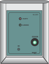
Every status determining room (FREE-OCCUPIED) is equipped with one control set (US). The control set is connected to the connecting terminal (PT), which can be mounted in/on the wall (with mounting box) near the table (desk) from whom the one can determine the room status. In front of the room there is one room signal lamp (SSL) which denotes its status by means of color code (green/red).

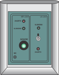
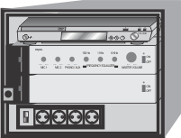
There are the central indicating panel (CIP), microphone paging unit (MPJ) and supply unit (NJ) in the nurse panel. By means of parallel indicating panel (PIP), all or part of information can be transferred to this room. The PIP is optionally switched on. Loudspeaker boxes are located in the waiting rooms to inform patients and staff on free rooms.

By switching on at FREE position in the control set (US), the following happens:
- green LED is lit on the control set
- green room signal lamp is lit
- green LED on the central indicating panel (CIP) is lit, also on the parallel indicating panel
(PIP), which represents paging room
- a short acoustic signal beeps on the CIP and PIP

The nurse is warned with acoustic signal, observes which room becomes free on the CIP (lit green LED). Similarly, free room can be observed on the PIP, too.
Using the microphone paging unit (MPJ), through the loudspeakers (ZI), nurse informs corresponding patient where to enter.
The nurse depresses the button SPEECH and speak to the microphone to transfer some information in the waiting room. During the depression, green LED above the push-button is lit.

The tone volume can be adjusted with push-buttons VOL(+,-) on the front face of MPJ unit.

Switching on in position OCCUPIED, on the US, the following happens:
- red LED is lit on the control set
- red room signal lamp is lit
- green LED on the central indicating panel (CIP) is lit, also on the parallel indicating panel
(PIP), which represents paging room
- there is no any acoustic signal, like in previous case,and the pult nurse is not warned.

If the control set switch-over is set in the middle position, all previuos signals are disabled, it means that the room is out of usage.


Site Meter